

How To Find Hi Speed Usb Port
TheSTM32 Development Board housing theSTM32F103C8 Microcontroller is getting increasingly popular thanks to its ARM Cortex M3 architecture, it has loftier operational speed and more peripheral options. Likewise since, this board can be easily programmed using the Arduino IDE information technology has become a preferable choice for many hobbyists and engineers for quick prototyping.
In our previous tutorial nosotros learnt the basics of the STM32 Development Board and also programmed it to blink an LED. Simply there was one huge drawback with information technology. In guild to programme the Board we utilised a FTDI programmer module and besides had to toggle the boot 0 jumper betwixt and 1 position while uploading and testing a code, which is surely a daunting task. Also the mini-USB port on the Development board was left totally unused. The reason for doing that is, when the STM32 evolution lath is purchasedit does non come with an Arduino ready boot loader and hence the lath will not be discovered by your computer when connected through the USB.
Hopefully though, there exists an experimental kick loader developed byLeafLabs for Maple mini boards. This kicking loader can be flashed into the STM32 once and thereafter nosotros can directly apply the USB port of the STM32 board to upload programs only like any other Arduino boards. Yet this kick loader is nevertheless in developmental stage at the fourth dimension of documenting this tutorial and is not advisable for critical applications. Before proceedings with this tutorial make sure you have read the previous tutorial to understand the basics of this board including details about the specifications and pin-outs.
Materials Required
- STM32 – (BluePill) Development Lath (STM32F103C8)
- FTDI Developer
- Breadboard
- Connecting wires
- Laptop with Net
Excursion Diagram
To program the STM32 Blue Pill lath directly through USB port we need to commencement wink the Maple boot loader into the MCU. To do this we need to utilize a Serial FTDI lath. This board is connected to the Rx and Tx pin of the STM32 as shown below.
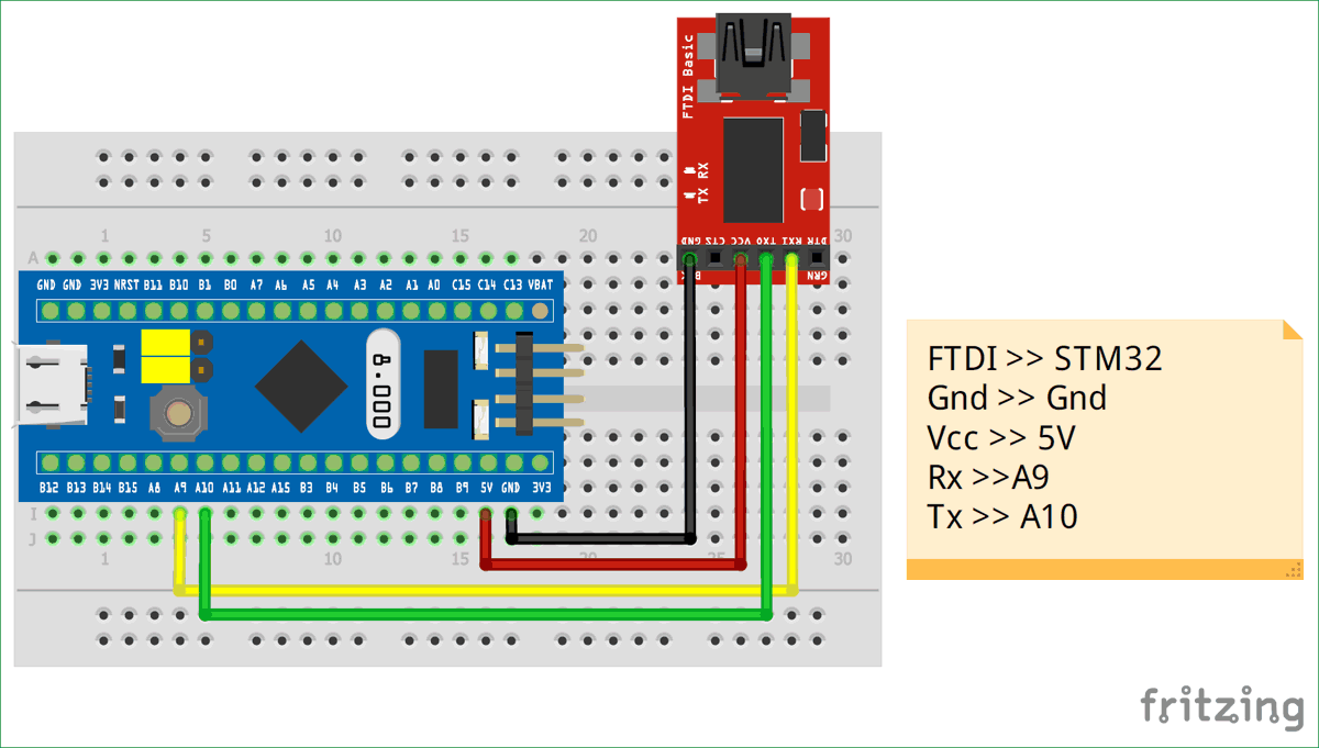
The Vcc pin of the FTDI board is connected to the STM32 5V pin of ability the board. The ground is connected to the Ground of STM32. The Rx and Tx pin of the FTDI board is connected to the A9 and A10 pivot of the STM32 respectively. Where the A9 is the Tx pin of STM32 MCU and the A10 is Rx pin.

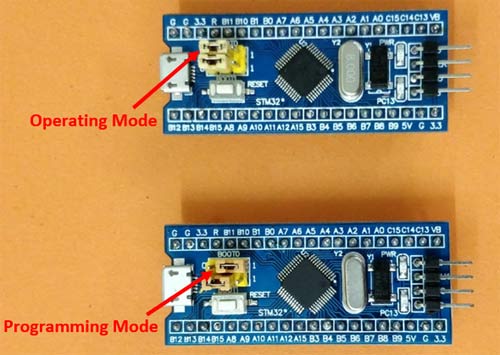
Make sure the boot 0 jumper pin on the board is gear up to 1 (programming mode) while uploading the boot loader. In one case the kick loader is flashed this pin tin be changed back to initial position (operating mode).
Uploading the Maple Boot loader to STM32 Development board
Once we accept made the to a higher place connexion connect the FTDI board to your computer and follow the steps to flash the boot loader into the STM32.
Step one: We take to download the boot loader program file binaries (bin file) form the github page. There are many versions of bin file, for the Bluish Pill board use this github link and click on the download button to download the bin file.
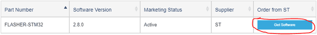
Step two: Adjacent we accept to download and install the STM Flash loader software to flash the downloaded bin file into STM32. Click on this link to get into the ST website and scroll to the lesser and click on get software
Footstep 3: To download the software you have to enter your E-mail address and the download link will be sent to your E-mail. Then follow the link back to the website and click on get software over again and you download will begin. Yeah it'southward a scrap frustrating simply this is how it should be washed. Don't forget to check your spam folder for the E-mail service, sometimes it takes a couple of minutes for the E-mail service to get in.
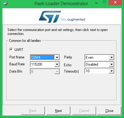
Step 4: Once downloaded install the software, make sure your STM32 lath is connect to your estimator though FTDI board so launch the software. The software will automatically notice the COM port if not utilize the Device manager and make sure y'all select the correct COM port number. In my instance it is COM4. Leave the rest of the setting every bit it is as shown below.
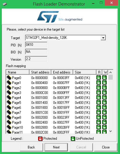
Step 5: Click on the Next push twice and the software volition over again automatically detect the lath details and display as shown beneath. The board we are using is STM32F1 with 128K flash memory.
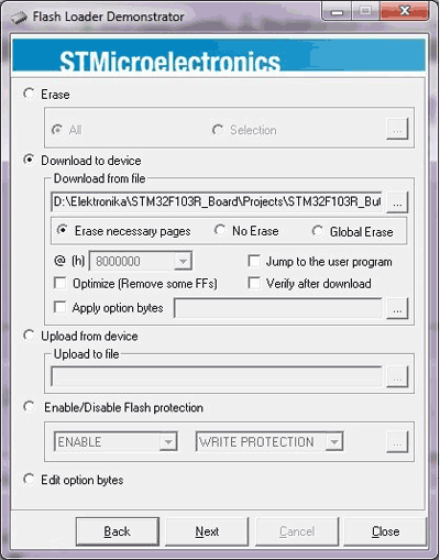
Stride 6: In the side by side stride, select Download to device and browse to the location where nosotros downloaded our bin file in step 1 and select it. Click on next.
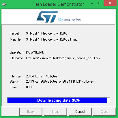
Step seven: The software will download some required files equally shown below and will then begin the procedure of flashing.
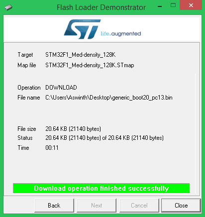
Footstep 8: Once the flashing is completes successfully, we will become the below screen. Click on close and exit the application. Nosotros have flashed the STM32 board with Arduino boot loader successfully. Now we take to prepare the Arduino IDE and install the drivers before we tin can program the STM32 board.
Preparing the Arduino IDE and Installing the Drivers
Follow the beneath steps to download and prepare the Arduino IDE to be used with the STM 32 Evolution board.
Step ane:- If you have non yet installed the Arduino IDE, download and install it from this link. Make sure you select your right operating system.
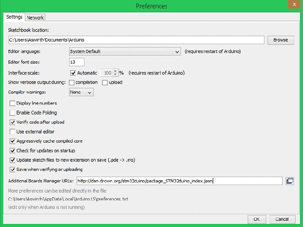
Footstep two:- Afterwards Installing the Arduino IDE open and download the required packages for the STM32 board. This tin exist done by selectingFile -> Preferences.
Step 3:- Clicking on Preferences will open the below shown dialog box. In the boosted Boards Manager URL text box paste the below link
http://dan.drown.org/stm32duino/package_STM32duino_index.json
and press OK.
Step 4:- Now go toTool -> Boards -> Board Manager. This will open the Boards manager dialog box, search for "STM32F1" and install the package that appears.
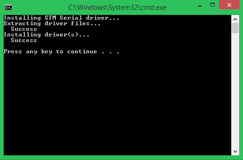
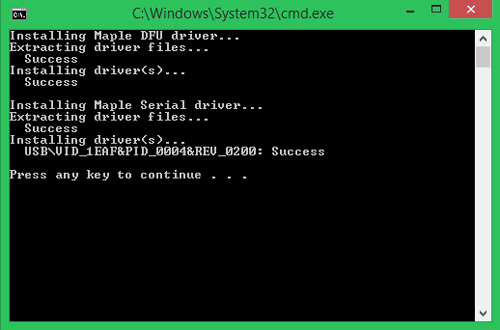
Step 5: Later on the package is installed, navigate to C:\Program Files (x86)\Arduino\hardware\Arduino_STM32-master\drivers\win where you will findinstall_drivers.bat andinstall_STM_COM_drivers.bat.
Step half-dozen: Click on both the bat files and install the drivers. You will get a DOS screen equally shown beneath.
Now the Arduino IDE is prepared for programming STM32 (Bluish Pill) Development Lath and the drivers are likewise installed.
Programming STM32 (Blue Pill) Direct Through USB Port
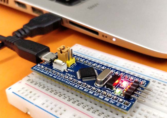
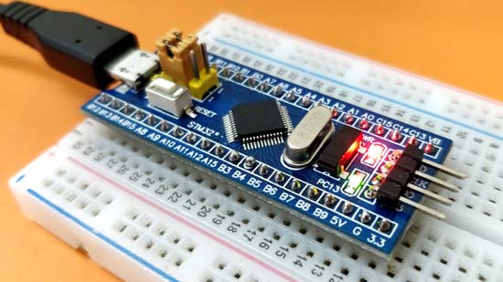
Remove the FTDI board and all the existing connections from yous STM32. Just use the micro-USB port on the STM32 board to connect it to the figurer every bit shown below. Brand certain thejumper 0 pin is positioned back at 0 (Operating mode). Time to come we need not toggle the jumper anymore to upload and run the programs.
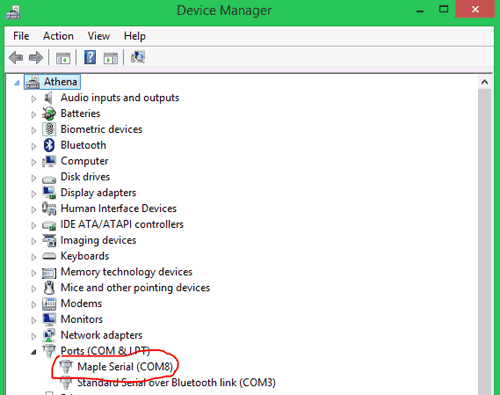
You computer should exist able to discover the Board at present. Wait for a while if yous come across any additional drivers getting installed. Then get intoDevice manager and bank check if your STM32 board is discovered under the COM and port department as shown below. Mine is connected to COM8 with the name Maple Mini.
Go toTools and whorl down to find the Generic STM32F103C series as shown below. Then brand certain the variant is64k Wink type, CPU speed is72MHz and change the upload method toSTM32duino Bootloader. As well select the correct COM port co-ordinate to the one on your device manager.
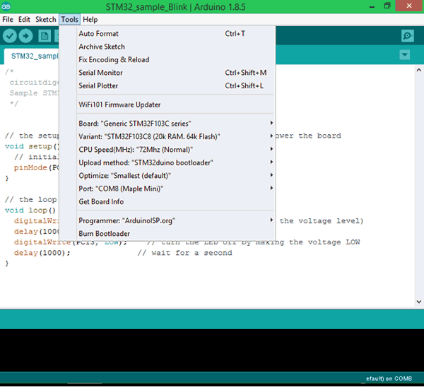
After all the changes are made, cheque the bottom right corner of the Arduino IDE and you should discover the post-obit setting being prepare. My STM32 board is connected to COM8 only yours might differ

Now the Arduino IDE is ready to program the STM 32 Blueish Pill Development Boards. Permit us upload the Sample Glimmer Programme from the Arduino IDE to the STM32 Bluish Pill lath to make sure everything is working properly. The instance program can be found at
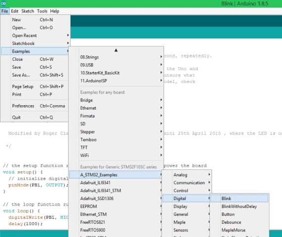
In the example program that opens,nosotros take to make a small alter. By default the program will exist written for PB1 merely on our board the on-board LED is connected to PC13then replace all PB1 with PC13 and we are skillful to keep. Thecomplete case programme which is modified can also be found at the bottom of this page.
The code inside theloop function alone is shown beneath, where nosotros can notice that the PC13 pivot is kept Loftier (on) for thou millisecond so turned LOW (off) for another 1000 millisecond and this is washed for space times since it is in loop function. Thus the LED appears to be blinking with an interval of thou millisecond.
digitalWrite(PC13, Loftier); // turn the LED on (High is the voltage level) delay(g); // await for a second digitalWrite(PC13, LOW); // plough the LED off past making the voltage low delay(thousand); // wait for a second
Press the upload button on the Arduino IDE and your programme should get compiled and uploaded. If everything has worked every bit expected then you should run across the following on your Arduino IDE console.
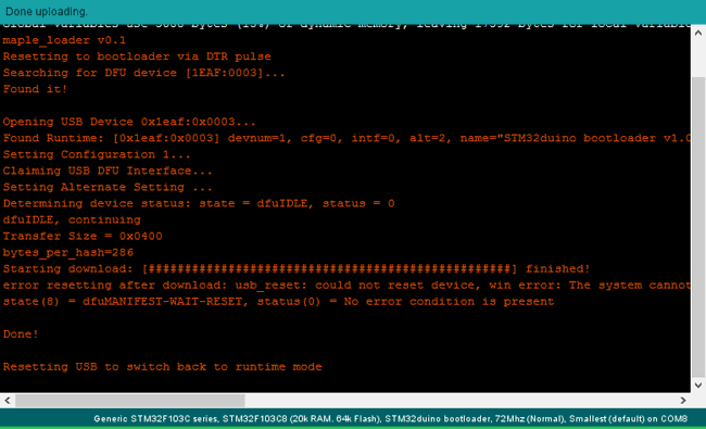
If the Program has been uploaded successfully then you should come across the Light-green LED blinking at a 1 second interval as shown in thevideo below. You tin also fiddle around with the program to increment or decrease the delay. Now yous can kickoff using the STM32 (Bluish Pill) Development board like whatever other Arduino boards, that is y'all no longer demand not change the position of jumpers or use external hardware to upload and test programs.
Hope you lot understood the tutorial and institute it useful toget started with STM32 Board. If you have any problem leave them in the comment section, also tell me what projects we should attempt with this STM32 lath in future.

Source: https://circuitdigest.com/microcontroller-projects/programming-stm32f103c8-board-using-usb-port
Posted by: adcoxhistiamseent.blogspot.com
0 Response to "How To Find Hi Speed Usb Port"
Post a Comment